Pages

Monday, 30 January 2017

Grinding V-Rails Part 1 Episode 134

Grinding V-Rails Part 1


This video shows the process I have used in past years to grind the V onto to angle iron to make V-Rails for my new CNC design. It uses a very simple jig, a small grinding wheel and the drillpress to put the V on the rail. It may not be everyones cup of tea but I find it simple to do and it gives me good results.


https://youtu.be/ATVB36-e3TU


How it's make

It consists of a small grinding wheel and a few offcuts of MFD.
I first cut a base out of MDF about 12" x 6"
I then cut another piece 7" x 12" which I then cut down the center to give 2 piece 3.5" x 12"
Screw one of these permanently down to the base and the other is screw into one of 2 positions depending on which side of the angle iron you are grinding. 

Alternatively use the method shown it the video and you will not have to change the jig to do the 2nd side of the angle iron.
The Grinding is done with a small 2 1/2" x 1/2" grindstone attached to a drill press.
The photos tell the story so I won't whitter on about it.

How to use


Set drill press speed to about 300RPM The faster you got the more heat you generate.
Set Jig on drill press table and ensure no more than 1/2" of of the stone covers the angle iron when cutting.
Put angle iron in jig and set height if grind wheel to the required height but only make small cuts.
Push angle iron into the wheel and hang on. The wheel will drag the steel through the jig so wear gloves. The steel does not need to be held down but apply downward pressure on it anyway just to make sure.
Did I mention Hold on to the steel. The wider the area is the more it will pull the steel through. You will not be able to feed the steel backward against the rotation of the grind wheel.
Make many small cuts not one big one. The cuts are very fast 4 foot in about 30 seconds.
HOLD ON TO THE STEEL.


Jig Construction


Jig with grindstone


Finished V-Rails


I hope you find this process useful. It would pay to practice on a small piece angle iron first to get the hang of how to do it before moving on to longer pieces.

Cheers
Peter

SHARE WITH OTHERS:
https://www.youtube.com/user/cncnutz

SOCIAL: 

https://www.cncnutz.com
https://www.youtube.com/user/cncnutz
https://www.facebook.com/CNCnutz
https://twitter.com/cncnutz


Sunday, 22 January 2017

New Y Axis Carriages Episode 133

I designed this back in 2012 and never got around to building it.
I honestly don't know if it will work as I hope but I do know one way of finding out. The one thing I know for sure is if I don't give it a try I will forever wonder if it would have worked.


Back in 2012 I designed a new Y Axis carriage for my machine partly because I could, but I also wanted to design something that could be built easily with limited tools and no specialist equipment.
I wanted to use steel and aluminum rather than wood or MDF for a rigid machine and I wanted it to be simple I kow if at least 1 machine that uses only 1 V-Bering on the bottom so I see no reason why this will not work in my design.
The steel parts are made from 12mm (1/2") steel strap and angle iron.
To date I have only designed the Y carriages but I prefer to build one piece and see how it goes before advancing to the next part. I have in mind some ideas for a X rail and X / Z carriage but I need the ensure that the part I have already designed works before forging ahead building other parts.
This will be a slow and cautious build and I will keep in mind that it needs to be made using readily available materials so that anyone can make it at home using what is available in most countries. For example in New Zealand I cannot get 8020 but have used an extrusion that is very similar to the 1530 extrusion that 8020 make in the USA. By moving 1 or 2 holes on some of the pieces to accomadate the slightly different slot positions am imperial version could be built.
The Rack and pinion drive system I will be taking from my existing machine and is one of the parts I believe are really needed to make a decent drive system. The Rack & pinion drive are an off the shelf part I purchased from the USA along with the rack and are well worth the investment. It turned a slow troublesome leadscrew machine I could stop with one hand into a speed demon which could push me backwards without a second thought. Rack and pinion is the way to go in my opinion and is one of the reason that large commercial machines use them for their X & Y axis. Suprisingly they are not as expensive as most people think and unlike leadscrew can be joined and don't whip at high speed.


Above is the original concept drawing I made all those years ago and while I have made a couple of changes it has kept the basic idea alive. I honestly don't know if it will work as I hope but I do know one way of finding out. The one thing I know for sure is if I don't give it a try I will forever wonder if it would have worked.

At this time there will be no plans for this build but in the future should it be successful I will look to drawing plans the various parts for those that wish to make their own.

As noted in the vide this project will be slow but it will eventually evolve to a full rebuild so don;t forget to subscribe to my Youtube channel so you can keep up with developments. Also sign up using the link above for and you will be emailed updates as they are made available.

Thanks for taking the time to view and feel free to comment.

Cheers
Peter

SHARE WITH OTHERS:
https://www.youtube.com/user/cncnutz

SOCIAL:
https://www.youtube.com/user/cncnutz
https://www.facebook.com/CNCnutz
https://twitter.com/cncnutz


Saturday, 14 January 2017

How to set your router perpendicular to the table top

How to set your router perpendicular to the table top


This weeks Top Tip come courtesy of Jim Anderson of Texas.
 
One of the most important adjustments you need to make on your router table is setting the router perpendicular to the tabletop. If you don't have this set right the cuts you make will have slanted sides and any pocket you make will not be flat and look grooved. They will be made up of a series of ramped cuts. The biggest problem is you can't use a square to ensure the cutter is perpendicular to the table so you need another method. Fortunately there is a simple trick that will allow you to set the router exactly.

Here's how


After posting the video above it was noted that there is an error in the demonstration of how to adjust the Router angle. The video below covers the correct method to adjust the router with respect to the table as well as info on surfacing a tabletop for tramming the machine using a method that will eliminate the ridges caused by an untrammed router. This new video needs to be viewed after the one shown above as it provides supplimentary information.


Original comment prompting the above video

By moving the eccentric bushings your Z axis is no longer square to the table. 
The way to do it is surface the entire table with a small router bit with a small step over first. Remove the router and square the Z axis to the table using machinist squares.  
Re-mount the router and continue with the technique you showed but only adjusting the router mount to the Z axis.
Depending how much correction you made your parts may come out smaller or larger than predicted and have small steps in the sides.

Building the Jig

Photos and description courtesy of Jim Anderson


1. I took a piece of wood about 1x1x15 inch long 
2. Drilled a hole on one end to hold a straight shaft (3/8 dia.)
3. Drilled a hole on the other end to hold a pencil (1/4 dia.)
4. Drilled 1/4 dia. holes for bolts to apply clamping pressure
5. Slotted each end of the wood to allow flex for clamping
6. Used a 1/4=20 bolts for clapping pressure
7. Moved the router to the center of the mill table and Power Off the Mill
8. Placed the straight shaft in the router (I used a Forester bit)
9. Placed a pencil in the wood and the bolts and tighten to hold the bit and pencil
10. Slide the pencil to touch the mill table
11. Rotate the device 90 degrees and validate the gap under the pencil
12. Make adjustments to the mill so that the gap is the same for 360 degrees


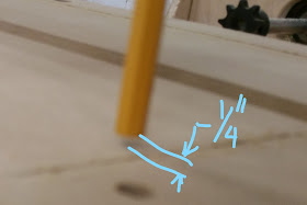
Pencil almost touching the table top


You can see here that the pencil is above the table top


The pencil is 1/4" above the table indicating the router is leaning to the left.


The router needs to be adjusted left and right back and forward until the gap remains constant under the pencil all the way around the table. Note that this process can only be done after the table top has been leveled at least once. A new tabletop could be sloping in any direction so an inital leveling profile must be run to flatten it with respect to the router.
The larger the distance between where it attaches to the router and where it is measured on the table the greater the accuracy so make it as big as practical.


If you would like notification of new videos please subscribe to my Youtube channel.

If you would like noticication of new articles on this website please subscribe using the "Follow by Email" on the right hand side. You will be notified as they are posted.


SHARE WITH OTHERS:
https://www.youtube.com/user/cncnutz

SOCIAL:
https://www.youtube.com/user/cncnutz
https://www.facebook.com/CNCnutz
https://twitter.com/cncnutz


Wednesday, 4 January 2017

How to install Mach3 Screensets - Episode 130

How to install Mach3 Screensets and more


A question from a subscriber asked how to install a Mach3 screenset and add a customised splash screen when Mach3 starts. Also where the configure is held for your pendant configuration. This video covers where you can download some of the available screensets for Mach3 and how to go about installing them. It really is surprisingly easy.


Where to get screensets

If you would like to download and install one of the screensets used in the video or would like to try out some of the others available, follow the link below. Please note that not all of the screensets on this page are free.


Mach3 Screensets


Custom Splash screens

To make your own custom splash screen you need to make a picture 400 x 240 pixels and save it as a BMP file. Replace the 3 files splash.bmp, splash1.bmp and splash2.bmp with your new pictures and ensure they have the same names. These will be found in the C:\Mach3\Bitmaps folder unless you changed the default location of Mach3.
You need all 3 files as they are displayed randomly at startup and if you only have 1 image it will show up only once every 3 or 4 starts. If you would like it to show the same image each time just make each image the same. If you prefer to see no splash screen then delete the 3 files and do not replace them.


Backup your Pendant Setting

Pendant settings are stored in 2 different places within Mach3.
The hotkeys that map the X,Y,Z,A,B and C axis are stored in the custom XML file you created for your machine. These are configured from the Mach3 'Config / System Hotkey' menu.
When it comes to configuring the other keys on the Pendant you need to use the Mach3sceen software which allows you to customise the screenset itself and map pendant keys to the various buttons shown in the screenset. It is a very powerful tool and if you would like to know more about how to customise you pendant please have a look here.


How to customise the Mach3 Pendant


SHARE WITH OTHERS:
https://www.youtube.com/user/cncnutz

SOCIAL:
https://www.youtube.com/user/cncnutz
https://www.facebook.com/CNCnutz
https://twitter.com/cncnutz